Introduction to Logic Gates
Imagine you want to create a machine that can make decisions based on certain conditions. To solve this problem, we can use logic gates, which help machines understand what to do in different situations. These gates can be combined to form more complex decision-making systems, enabling us to build various devices like calculators, computers, and even self-driving cars.
A logic gate is like a simple question with a "yes" or "no" answer. For example, "Is it raining?" can be answered with "yes" (1) or "no" (0). Envision logic gates as the digital world's magical puzzle pieces that come together to form the complex circuits powering our everyday electronic devices. These gates operate with binary inputs, 0 or 1, and create an output based on the specific combination of input values. In a machine, a logic gate takes two inputs (0 or 1) and gives an output (also 0 or 1) based on the inputs. By combining different types of logic gates, such as AND, OR, NOT etc. machines can make more complex decisions.
To better understand logic gates, we can learn about Boolean algebra, a type of math that deals with true (1) and false (0) values. This helps us design and optimize digital systems using logic gates, forming the basis for advanced digital systems like microprocessors and memory devices.
Once we grasp the fundamentals of logic gates, we can explore the complexities of creating digital circuits, such as combinational and sequential circuits. This knowledge opens the door to cutting-edge fields like Very Large Scale Integration (VLSI) design, quantum computing, and novel computing architectures.
In the next section, we will learn how to practically verify the workings of logic gates using Proteus software, an amazing platform for simulating electronic circuits and bringing them to life. This hands-on activity will provide a deeper understanding of logic gates and their functions, allowing you to appreciate their crucial role in the world of digital systems.
Types of Logic Gates and IC Numbers
Let's examine the seven main types of logic gates, their corresponding integrated circuit (IC) numbers, and their characteristics:
- AND gate (IC 7408): Outputs 1 only when both inputs are 1. It uses a two-input AND operation, symbolized as A ⋅ B. AND gates can be cascaded to create multi-input AND gates.
- OR gate (IC 7432): Outputs 1 when at least one input is 1. It uses a two-input OR operation, represented as A + B. OR gates can also be cascaded for multi-input functionality.
- NOT gate (IC 7404): Inverts the input, turning 1 into 0 and vice versa. It uses a single-input NOT operation, denoted as ¬A or A̅. NOT gates are often combined with other gates to create complex operations.
- NAND gate (IC 7400): A combination of AND and NOT gates, outputs 0 only when both inputs are 1. It uses a two-input NAND operation, symbolized as A ⋅ B with an overbar. NAND gates are universal, meaning they can be combined to form any other gate.
- NOR gate (IC 7402): A combination of OR and NOT gates, outputs 1 only when both inputs are 0. It uses a two-input NOR operation, represented as A + B with an overbar. Like NAND gates, NOR gates are also universal.
- XOR gate (IC 74LS86): Outputs 1 when inputs are different and 0 when they are the same. It uses a two-input XOR operation, denoted as A ⊕ B. XOR gates are widely used in error detection and correction circuits.
- XNOR gate (IC 4077): The opposite of XOR, outputs 1 when inputs are the same and 0 when they are different. It uses a two-input XNOR operation, symbolized as A ⊕ B with an overbar. XNOR gates play a key role in parity checkers and adder circuits.
Requirements: Computer (Windows OS recommended), Proteus software
Proteus Setup and General Direction
To start exploring logic gates using Proteus, follow these simple steps:
- Open the Proteus software.
- Create a new project.
- Add the IC for the desired logic gate to the design.
- Connect input and output pins to switches and LED indicators, respectively.
- Run the simulation and test the truth table by toggling the switches.
Procedures of Doing the Experiment
AND Gate
Title
Verification of all Logic Gate's Truth Table Using Proteus Software
Aim
To validate the truth table of an AND logic gate through Proteus software simulation.
Requirements
Proteus software, 7408 AND gate IC, Logic State, and Logic Probe tools.
Theory
An AND gate performs a logical conjunction between input signals. The output is true (1) only when all inputs are true (1). The truth table of an AND gate lists input-output combinations, providing a basis for verifying the gate's functionality in a simulation.
Truth Table of AND Gate (7408)
| Input: A | Input: B | Output |
|---|---|---|
| 0 | 0 | 0 |
| 0 | 1 | 0 |
| 1 | 0 | 0 |
| 1 | 1 | 1 |
Procedure
- Open Proteus, create a new project and open schematic capture.
- Add the 7408 AND gate IC, Logic State, and Logic Probe (Big) from the pick device menu to the dashboard.
- Place the AND gate, Logic State, and Logic Probe tools onto the schematic.
- Connect the components, run the simulation, and observe the output for input combinations "00", "01", "10", "11".
- Verify the simulation results against the expected truth table of an AND gate.
Result
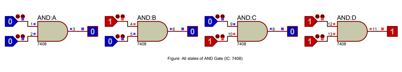
The simulation results match the AND gate truth table, validating its correct functionality.
Conclusion
The AND gate truth table has been successfully verified using Proteus software, confirming its proper operation in digital circuits.
OR Gate
Title
Verification of all Logic Gate's Truth Table Using Proteus Software
Aim
To validate the truth table of an OR logic gate through Proteus software simulation.
Requirements
Proteus software, 7432 OR gate IC, Logic State, and Logic Probe tools.
Theory
An OR gate performs a logical disjunction between input signals. The output is true (1) if any of the inputs are true (1). The truth table of an OR gate lists input-output combinations, providing a basis for verifying the gate's functionality in a simulation.
Truth Table of OR Gate (7432)
| Input: A | Input: B | Output |
|---|---|---|
| 0 | 0 | 0 |
| 0 | 1 | 1 |
| 1 | 0 | 1 |
| 1 | 1 | 1 |
Procedure
- Open Proteus, create a new project and open schematic capture.
- Add the 7432 OR gate IC, Logic State, and Logic Probe (Big) from the pick device menu to the dashboard.
- Place the OR gate, Logic State, and Logic Probe tools onto the schematic.
- Connect the components, run the simulation, and observe the output for input combinations "00", "01", "10", "11".
- Verify the simulation results against the expected truth table of an OR gate.
Result
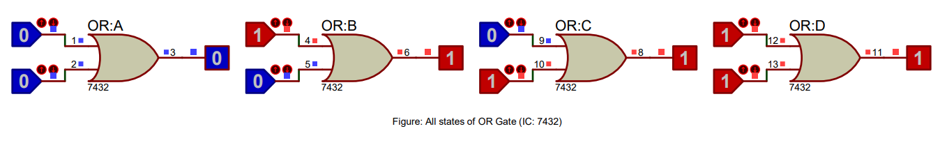
The simulation results match the OR gate truth table, validating its correct functionality.
Conclusion
The OR gate truth table has been successfully verified using Proteus software, confirming its proper operation in digital circuits.
NOT Gate
Title
Verification of all Logic Gate's Truth Table Using Proteus Software
Aim
To validate the truth table of a NOT logic gate through Proteus software simulation.
Requirements
Proteus software, 7404 NOT gate IC, Logic State, and Logic Probe tools.
Theory
A NOT gate, also known as an inverter, performs a logical negation of the input signal. The output is true (1) when the input is false (0) and vice versa. The truth table of a NOT gate lists input-output combinations, providing a basis for verifying the gate's functionality in a simulation.
Truth Table of NOT Gate (7404)
| Input | Output |
|---|---|
| 0 | 1 |
| 1 | 0 |
Procedure
- Open Proteus, create a new project and open schematic capture.
- Add the 7404 NOT gate IC, Logic State, and Logic Probe (Big) from the pick device menu to the dashboard.
- Place the NOT gate, Logic State, and Logic Probe tools onto the schematic.
- Connect the components, run the simulation, and observe the output for input values "0" and "1".
- Verify the simulation results against the expected truth table of a NOT gate.
Result
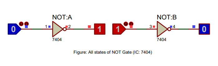
The simulation results match the NOT gate truth table, validating its correct functionality.
Conclusion
The NOT gate truth table has been successfully verified using Proteus software, confirming its proper operation in digital circuits.
NAND Gate
Title
Verification of all Logic Gate's Truth Table Using Proteus Software
Aim
To validate the truth table of a NAND logic gate through Proteus software simulation.
Requirements
Proteus software, 7400 NAND gate IC, Logic State, and Logic Probe tools.
Theory
A NAND gate is a combination of an AND gate followed by a NOT gate. The output is false (0) only when all inputs are true (1). The truth table of a NAND gate lists input-output combinations, providing a basis for verifying the gate's functionality in a simulation.
Truth Table of NAND Gate (7400)
| Input: A | Input: B | Output |
|---|---|---|
| 0 | 0 | 1 |
| 0 | 1 | 1 |
| 1 | 0 | 1 |
| 1 | 1 | 0 |
Procedure
- Open Proteus, create a new project and open schematic capture.
- Add the 7400 NAND gate IC, Logic State, and Logic Probe (Big) from the pick device menu to the dashboard.
- Place the NAND gate, Logic State, and Logic Probe tools onto the schematic.
- Connect the components, run the simulation, and observe the output for input combinations "00", "01", "10", "11".
- Verify the simulation results against the expected truth table of a NAND gate.
Result
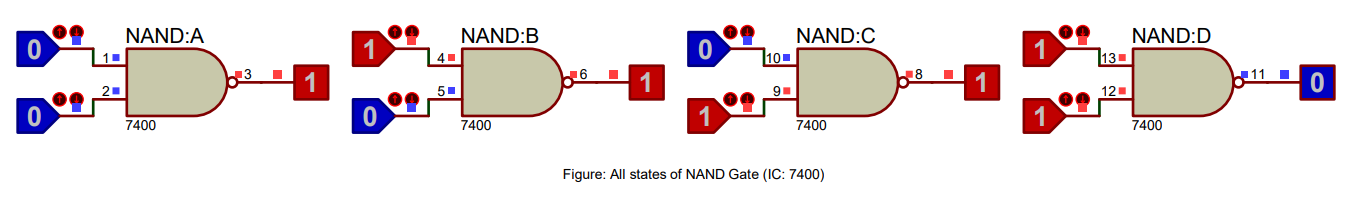
The simulation results match the NAND gate truth table, validating its correct functionality.
Conclusion
The NAND gate truth table has been successfully verified using Proteus software, confirming its proper operation in digital circuits.
NOR Gate
Title
Verification of all Logic Gate's Truth Table Using Proteus Software
Aim
To validate the truth table of a NOR logic gate through Proteus software simulation.
Requirements
Proteus software, 7402 NOR gate IC, Logic State, and Logic Probe tools.
Theory
A NOR gate is a combination of an OR gate followed by a NOT gate. The output is true (1) only when all inputs are false (0). The truth table of a NOR gate lists input-output combinations, providing a basis for verifying the gate's functionality in a simulation.
Truth Table of NOR Gate (7402)
| Input: A | Input: B | Output |
|---|---|---|
| 0 | 0 | 1 |
| 0 | 1 | 0 |
| 1 | 0 | 0 |
| 1 | 1 | 0 |
Procedure
- Open Proteus, create a new project and open schematic capture.
- Add the 7402 NOR gate IC, Logic State, and Logic Probe (Big) from the pick device menu to the dashboard.
- Place the NOR gate, Logic State, and Logic Probe tools onto the schematic.
- Connect the components, run the simulation, and observe the output for input combinations "00", "01", "10", "11".
- Verify the simulation results against the expected truth table of a NOR gate.
Result
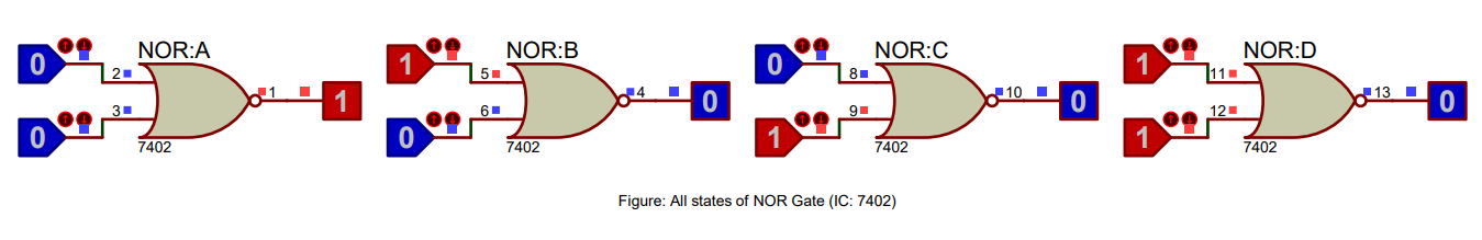
The simulation results match the NOR gate truth table, validating its correct functionality.
Conclusion
The NOR gate truth table has been successfully verified using Proteus software, confirming its proper operation in digital circuits.
XOR Gate
Title
Verification of all Logic Gate's Truth Table Using Proteus Software
Aim
To validate the truth table of an XOR logic gate through Proteus software simulation.
Requirements
Proteus software, 74LS86 XOR gate IC, Logic State, and Logic Probe tools.
Theory
An XOR gate, also known as an Exclusive OR gate, performs a logical exclusive disjunction between input signals. The output is true (1) only when the number of true inputs is odd. The truth table of an XOR gate lists input-output combinations, providing a basis for verifying the gate's functionality in a simulation.
Truth Table of XOR Gate (74LS86)
| Input: A | Input: B | Output |
|---|---|---|
| 0 | 0 | 0 |
| 0 | 1 | 1 |
| 1 | 0 | 1 |
| 1 | 1 | 0 |
Procedure
- Open Proteus, create a new project and open schematic capture.
- Add the 74LS86 XOR gate IC, Logic State, and Logic Probe (Big) from the pick device menu to the dashboard.
- Place the XOR gate, Logic State, and Logic Probe tools onto the schematic.
- Connect the components, run the simulation, and observe the output for input combinations "00", "01", "10", "11".
- Verify the simulation results against the expected truth table of an XOR gate.
Result
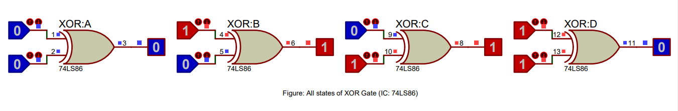
The simulation results match the XOR gate truth table, validating its correct functionality.
Conclusion
The XOR gate truth table has been successfully verified using Proteus software, confirming its proper operation in digital circuits.
XNOR Gate
Title
Verification of all Logic Gate's Truth Table Using Proteus Software
Aim
To validate the truth table of an XNOR logic gate through Proteus software simulation.
Requirements
Proteus software, 4077 XNOR gate IC, Logic State, and Logic Probe tools.
Theory
An XNOR gate, also known as an Exclusive NOR gate, performs a logical equivalence between input signals. The output is true (1) when the number of true inputs is even. The truth table of an XNOR gate lists input-output combinations, providing a basis for verifying the gate's functionality in a simulation.
Truth Table of XNOR Gate (4077)
| Input: A | Input: B | Output |
|---|---|---|
| 0 | 0 | 1 |
| 0 | 1 | 0 |
| 1 | 0 | 0 |
| 1 | 1 | 1 |
Procedure
- Open Proteus, create a new project and open schematic capture.
- Add the 4077 XNOR gate IC, Logic State, and Logic Probe (Big) from the pick device menu to the dashboard.
- Place the XNOR gate, Logic State, and Logic Probe tools onto the schematic.
- Connect the components, run the simulation, and observe the output for input combinations "00", "01", "10", "11".
- Verify the simulation results against the expected truth table of an XNOR gate.
Result
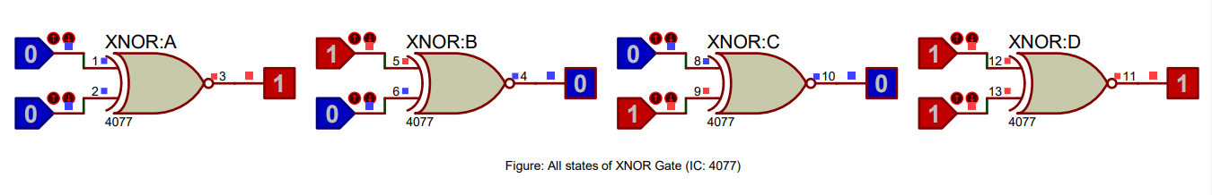
The simulation results match the XNOR gate truth table, validating its correct functionality.
Conclusion
The XNOR gate truth table has been successfully verified using Proteus software, confirming its proper operation in digital circuits.
Summary
In this series of experiments, we have successfully verified the truth tables of AND, OR, NOT, NAND, NOR, XOR, and XNOR logic gates using Proteus software. The observed results match the expected truth tables, which validates the functionality of these gates in Proteus software. This provides students with an effective way to learn and understand the behavior of various logic gates and to develop their skills in digital circuit design and simulation.